|
||||||||||||||||||||||
For advertising opportunities, please email info_at_ raidrecoveryguide.com |
RAID Data RecoveryRAID Rebuilding
When a failed drive is replaced, the data that was removed from the array with its departure must be regenerated on the new disk by the RAID controller, a process called rebuilding. An array is vulnerable while it is running in a degraded state. Until the failed drive is replaced and its data rebuilt, the array provides no redundancy. Consequently, it's not a good idea to put off rebuilding a degraded array; you're putting your data at risk! RAID Data Recovery ProcessRAID systems are susceptible to the same ailments that plague single hard drives, such as viruses, logical problems, human error, and physical damage. Moreover, due to their complexity, they may suffer from additional points of failure, such as lost server registry configurations, accidental RAID drive reconfigurations, RAID controller failures and multiple drive failures. If multiple drives fail, or other serious problems occur in a RAID, your data may be compromised. Under such circumstances, if you fail to make a proper backup, you may have to call a data recovery company. Many have high success rates when it comes to RAID data recovery. Using specialized facilities, equipment, and software, they can even recover data from a moribund hard drive. If the data is worth money, don't chance it!Reputable recovery companies all follow a standard set of RAID data recovery procedures. This usually includes an initial evaluation, where technicians carefully examine the array to diagnosis the exact nature of the problem. During this time, they'll also attempt to make an image of the failed hard drives. The RAID data recovery specialists will then extract the data from the image, and work to piece it together. If successful, they will restore your data onto the media of your choice. By far the most reputable data recovery companies are as follows: Top Companies Our #1 pick: ESS Data Recovery (datarecovery.com) offers a wide range of service levels with turnaround time from 1-10 days depending on your budget and needs. They are not only affordable, but hugely successful, especially in the RAID recovery industry, with clients ranging from small schools to Lockheed Martin and NASA. They also offer extensive information about RAID recovery on their website: RAID Data Recovery. Our #2 pick: UK-based Data Recovery services for hard disks, raid, memory cards, VM and tape. From all manufacturers of desktop, server and laptop computers. From internal and external hard disks, solid state devices and all other computer storage media. We offer a free diagnosis and a no recovery no fee policy on all standard services. Our #3 pick: Austrailia-based Data Recovery Services P/L is a full service data recovery company serving all of Australia and Asia Pacific. This organization was established in 1991 in the United Kingdom and in 1996 in Australia. They claim to be the oldest company in Australia devoted exclusively to recovering data, with more than 15 years of experience.
RAID Data Recovery Methods If you do not think sending your RAID to a data recovery company is in your interest, you may want to try to recover the RAID yourself so we are providing detailed information about how to recover RAID systems with a hex editor. USE AT YOUR OWN RISK. Recovery companies ALWAYS make several bit-level backups of each hard drive before any RAID recovery procedure is performed. ***USE AT YOUR OWN RISK*** This information is provided AS-IS. The owners of this website make no representation as to the accuracy or completeness of this information. Use at your own risk, and always make backups of your disks before performing any data recovery procedure. This information is for your own personal use. None of this information may be reprinted or republished without the express written consent of the website owners who may be contacted by emailing: info{at}raidrecoveryguide.com. RAID RECOVERY RAID LEVEL ZERO RECOVERY RAID zero is simply blocks of data striped between two disks. Block size can be anything, but is typically 64kB (128 sectors) Disk 0 will contain the first sector 0 through 127, disk 1 will contain sectors 128 through 255, and this will continue to alternate throughout the entire virtual disk. One complication can be expected in some cases, and that is the presence of an offset. An offset is a number of sectors before the first striped block. The presence of an offset is common in Adaptec cards. The offset can easily be found by searching for the partition table. When found, simply take the sector number where the partition table is located, and clone the disk to a file starting with this sector. The next step is to find the stripe size. This is a very critical step and you must be absolutely sure. Typically the stripe size will be the same as the default setting for the card that was used. For instance, a Dell PERC 2 adaptec RAID card has a stripe size of 32K (64 sectors) and an offset of 64K (128 sectors).� Use this as your starting point if possible. If you do not know the card type used, it is wise to use 64K (128 sectors) as your starting point as this is most common among all cards.� Now use Winhex to find a location on the disk that is easy to see a pattern. See the example below.� Notice above how we have text, apparently from a database of some sort. This text can be used to identify a data pattern. Now look at the current sector (53,721,904).� Divide this number by the suspected stripe size in sectors. In this case the stripe size we are attempting to validate is 128 sectors. The resulting number will probably not be a whole number. In this case it is 419702.375. Take the whole number of 419702 and multiply this by the suspected stripe size (128). The resulting number is what we will refer to as the �stripe break point.� It is necessary to know this simple calculation for all types of RAID except RAID 1 (mirroring).
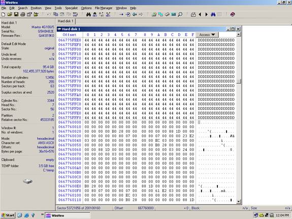
Find the break point: 53721904/128=419702.375 419702*128 = 53721856 Answer: A break point is located at sector 53, 721, 856 (see illustration below) Notice how at the exact break point of 53, 721,
856 we have a definite difference of data.�
This is because the stripe is from a separate area of the
volume. Not all break points will be this easy. In some cases you
will have to look at the actual data and determine if consistency
exists. Train your eyes to catch a break point while you are scrolling
the sectors using the �page down� function, and you will become
very proficient.� You will
often have to repeat the steps above on different areas of the disk
if the data is too inconsistent to determine the break point. Once the break point is discovered, you will then
be able to start the de-striping process.�
Using a software utility, such as the hex editor Winhex,
place the disk images in the proper order, adjust the stripe size,
and clone to a hard disk. Once complete, the disk should be mountable.
Refer to the partition and boot sector repair section of this manual
if the disk is not mountable, or review the stripe break points. RAID Level 5 Recovery Definition: RAID 5 is a very popular RAID level
that uses block level striping and distributed parity. This level
tries to remove the bottleneck of the dedicated parity drive. With
the use of a distributed parity algorithm, this level writes the
data and parity data across all the drives. Basically, the blocks
of data are used to create the parity blocks which are then stored
across the array. This removes the bottleneck of writing to just
one parity drive. However, the parity information still has to be
written on a separate disk whenever a write occurs, so the slowdown
involved with that still applies. There is also a small calculation
that must take place for every write.�
The fault tolerance is maintained by separating the parity
information for a block from the actual data block. This way when
one drive fails, the array goes into �degraded� mode and begins
reading and writing to the parity areas on the other disks in place
of that bad drive. When a new disk is placed back into the RAID,
the controller or software begins copying the parity data back to
the new drive until complete, then the array will kick out of degraded
mode.� Recovery is more complicated
than usual because of the distributed nature of the parity. Many
RAID cards and software use separate and sometimes proprietary algorithms
to generate the parity stripes. On illustration A you see just one
example of RAID 5, generally referred to as �standard� or �straight�
RAID 5. Many times you can get the striping pattern from the RAID
card or software manufacturer. Disk One��������
����������� ������� Disk Two����������������������� ������ Disk
Three����������������������� Disk
Four
As you can see in the illustration above, there is a clear
pattern. The sectors in the virtual disk are striped evenly across
the disks, but every fourth stripe is dedicated to parity. Red denotes
parity data. Controller Requirements: Supported by most hardware controllers, both SCSI and IDE/ATA, and also most software RAID solutions. Hard Disk Requirements: Minimum of three hard. Any type may be used, but they should be of identical type and size for best performance and to eliminate "waste". Array Capacity: (Size of Smallest Drive * Number of Drives � Smallest Drive). Fault Tolerance: Any one drive may fail and the array continues to operate (in fact, it operates faster in degraded mode!)� Failure of another drive results in loss of all data, which is why you paid the big bucks! Storage Efficiency: 75% if identical drives are used. Availability: Loss of one disk = continued server functionality. Rebuilding (Scrubbing) and Degradation: Rebuilding takes place automatically with most RAID cards and software. Random Read Performance: Excellent Random Write Performance: Moderate Sequential Read Performance: Moderate Sequential Write Performance: Very good. RAID RECOVERY RAID 5 DATA RECOVERY RAID five uses a distributed parity algorithm,
this level writes the data and parity data across all the drives.
The blocks of data are used to create the parity blocks which are
then stored across the array. Block size can be anything, but is
typically 64kB (128 sectors) Disk 0 will contain the first sector
0 through 127, disk 1 will contain sectors 128 through 255, and
this will continue to alternate until you reach the last disk of
the set, and this disk will be the parity disk. The parity disk
will rotate based on the parity rotation algorithm for that particular
RAID card or software.� One complication can be expected in some cases,
and that is the presence of an offset. An offset is a number of
sectors before the first striped block. The presence of an offset
is common in Adaptec cards. The offset can easily be found by searching
for the partition table. When found, simply take the sector number
where the partition table is located, and clone the disk to a file
starting with this sector. Repeat on all drives and you have a starting
point! The next step is to find the stripe size. This
is a very critical step and you must be absolutely sure. Typically
the stripe size will be the same as the default setting for the
card that was used. For instance, a Dell PERC 2 adaptec RAID card
has a stripe size of 32K (64 sectors) and an offset of 64K (128
sectors).� Use this as your
starting point if possible. If you do not know the card type used,
it is wise to use 64K (128 sectors) as your starting point as this
is most common among all cards.� Now use Winhex to find a location on the disk that
is easy to see a pattern. See the example below.�
Notice how we have text, apparently from a database of some
sort. This text can be used to identify a data pattern. Now look
at the current sector (53,721,904).�
Divide this number by the suspected stripe size in sectors.
In this case the stripe size we are attempting to validate is 128
sectors. The resulting number will probably not be a whole number.
In this case it is 419702.375. Take the whole number of 419702 and
multiply this by the suspected stripe size (128). The resulting
number is what we will refer to as the �stripe break point.� It
is necessary to know this simple calculation for all types of RAID
except RAID 1 (mirroring). Find the break point: 53721904/128=419702.375 419702*128 = 53721856 Answer: A break point is located at sector 53,
721, 856 Notice above how we have text, apparently from
a database of some sort. This text can be used to identify a data
pattern. Notice how at the exact break point of 53, 721,
856 we have a definite difference of data.�
This is because the stripe is from a separate area of the
volume. Not all break points will be this easy. In some cases you
will have to look at the actual data and determine if consistency
exists. Train your eyes to catch a break point while you are scrolling
the sectors using the �page down� function, and you will become
very proficient.� You will
often have to repeat the steps above on different areas of the disk
if the data is too inconsistent to determine the break point. Once the break point is discovered, you will then be able to start the RAID 5 de-striping process.� Assuming you have no idea where the disks belong
in the RAID then you must find a point on the disk where the data
is sequential. This is very difficult unless the volume is formatted
with NTFS, FAT32, or FAT16. In this case, you can use the Master
boot record and NTFS/FAT32/FAT16 boot record to find the location
of the MFT files or FAT tables. RAID-5 Parity Rotation RAID-5 under any operating system can use
one of four algorithms for the placement of segments among the disks
in the array. -Keep in mind
in your troubleshooting that there may be an offset throwing everything
off. Find the partition table or OS identifier and us this as your
definite sector 0. In a RAID 5 there should be two drives with a
partition table. One is the first drive in that array and one is
the last drive in the array. Right Synchronous Left Synchronous, Left Asynchronous Left Asynchronous (Backwards Parity Rotation, Standard) In this layout, the segments are numbered
sequentially, starting with the first non-parity drive in the stripe.
The parity drive starts at the last drive, and moves backwards one
drive per stripe. While this is the hardware 'standard' RAID-5 layout,
it is not the default for Linux or Windows 2000, 2003 Server. This
is sometimes called backwards parity or �Standard Rotation� R-studio
supports this mode.
Left Synchronous In this layout, the segments are numbered
sequentially, starting with the first drive in the stripe after
the parity. The segments wrap. The parity drive starts at the left-most
drive, and moves right one drive per stripe. This is the default
RAID-5 segment layout under Linux. For large reads, this segment layout is the fastest. This
is because each consecutive group of segments that is no larger
than the total number of disks in the array, will use all the disks
in the array.
Right Asynchronous (Forward Parity Rotation) In this layout, the segments are numbered sequentially,
starting with the first non-parity drive in the stripe. The parity
drive starts at the right-most drive, and moves left one drive per
stripe.
Right Synchronous
Refer to the partition and boot sector repair section of this manual if the disk is not mountable, or review the stripe break points. RAID Level 3 Recovery Definition: Bit-Interleaved Parity: This level uses byte level striping with dedicated parity. In other words, data is striped across the array at the byte level with one dedicated parity drive holding the redundancy information. The idea behind this level is that striping the data increasing performance and using dedicated parity takes care of redundancy. 3 hard drives are required. 2 for striping, and 1 as the dedicated parity drive. Although the performance is good, the added parity does slow down writes. The parity information has to be written to the parity drive whenever a write occurs. This increased computation calls for a hardware controller, so software implementations are not practical. RAID 3 is good for applications that deal with large files since the stripe size is small. Since this level is so rare, we have not come up with a recovery procedure for this RAID level. Recovery is possible by finding the parity disk using the image compression technique, then removing it and treating the RAID as a stripe. RAID Level 4 Recovery This level is very similar to RAID 3. The only difference is that it uses block level striping instead of byte level striping. The advantage in that is that you can change the stripe size to suit application needs. This level is often seen as a mix between RAID 3 and RAID 5, having the dedicated parity of RAID 3 and the block level striping of RAID 5. Again, you'll probably need to eliminate the parity disk using the image compression technique, then removing it and treating the RAID as a stripe. RAID Level 10 and 0 + 1 Recovery Combining Levels of RAID The single RAID levels don't always address every� requirement that exists. To address these different requirements, someone thought of the idea of combining RAID levels. What if you can combine two levels and get the advantages of both? This was the motivation behind creating these new levels. The main benefit of using multiple RAID levels is the increased performance. Usually combining RAID levels means using a hardware RAID controller. The increased level of complexity of these levels means that software solutions are not practical. RAID 0 has the best performance out of the single levels and it is the one most commonly being combined. Not all combinations of RAID levels exist. The most common combinations are RAID 0+1 and 1+0. The difference between 0+1 and 1+0 might seem subtle, and sometimes companies may use the terms interchangeably. However, the difference lies in the amount of fault tolerance. Both these levels require at least 4 hard drives to implement. Let's look at RAID 0+1 first. This combination uses RAID 0 for it's high performance and RAID 1 for it's high fault tolerance. I actually mentioned this level when I talked about adding striping to mirroring. Let's say you have 8 hard drives. You can split them into 2 arrays of 4 drives each, and apply RAID 0 to each array. Now you have 2 striped arrays. Then you would apply RAID 1 to the 2 striped arrays and have one array mirrored on the other. If a hard drive in one striped array fails, the entire array is lost. The other striped array is left, but contains no fault tolerance if any of the drives in it fail. RAID 1+0 applies RAID 1 first then RAID 0 to the drives. To apply
RAID 1, you split the 8 drives into 4 sets of 2 drives each. Now
each set is mirrored and has duplicate information. To apply RAID
0, you then stripe across the 4 sets. In essence, you have a striped
array across a number of mirrored sets. This combination has better
fault tolerance than RAID 0+1. As long as one drive in a mirrored
set is active, the array can still function. So theoretically you
can have up to half the drives fail before you lose everything,
as opposed to only two drives in RAID 0+1. The popularity of RAID
0+1 and 1+0 stems from the fact that it's relatively simple to implement
while providing high performance and good data redundancy. With
the increased reduction of hard drive prices, the 4 hard drive minimum
isn't unreasonable to the mainstream anymore. However, you still
have the 50% waste in storage space whenever you are dealing with
mirroring. Again, we must narrow these types of RAID arrays down to its simplest
form. Utilizing the image compression technique will make this a
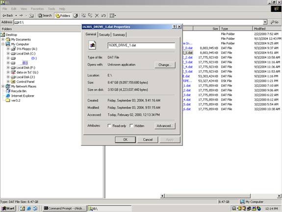
speedy process. Compressed Image Technique Compressed Image Technique The compressed image technique allows you to quickly
identify the following:
Simply make your RAID images using Winhex, but
store them on a compressed NTFS volume. Storing disk images on an
NTFS compressed volume also saves space and allows you to work more
quickly without having to shuffle many drives in your recovery attempts.
Simply right-click on the image to see its compressed size. See
the following example of a RAID five with one drive that failed
long before the second drive failed. On the following pages, see
if you can determine which disk does not belong. Do not pay attention
to subtle differences. |
|||||||||||||||||||||

 With
their built-in redundancy, RAID systems are able to continue functioning
even if a hard drive fails. When this happens however, performance
is negatively affected, and the RAID is said to be operating in
a degraded, or critical state. This occurs because the lost
information must be regenerated "on the fly" from the
parity data.
With
their built-in redundancy, RAID systems are able to continue functioning
even if a hard drive fails. When this happens however, performance
is negatively affected, and the RAID is said to be operating in
a degraded, or critical state. This occurs because the lost
information must be regenerated "on the fly" from the
parity data.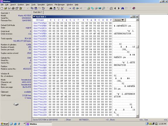


+ Home |
+ Basics |
||||